Many different pile patterns are supported in the analysis mode. They are single, triangular, default and custom rectangular pile pattern and circular pile patterns.
In the design mode, a minimum of three piles is used to support a pile-supported foundation. A symmetrical rectangular pattern is then considered. The number of piles is incremented until strength and spacing requirements of the overall foundation system are met. For octagonal foundations, a ring shaped pile pattern with even number of piles is generated.
For the applied loads, a pile layout pattern, which will meet the strength and spacing requirements, is determined. For a rectangular pile pattern, the number of piles are incremented in the X direction first and then in the Z direction to arrive at the minimum number of piles satisfying all the required criteria. For a circular or ring pile pattern, the program starts filling the piles from the outermost ring until it finds the minimum number of piles that will satisfy the required criteria.
Layout tab:
The pile layout dialog displays the different types of pile patterns possible. Selecting the icons at the top of the dialog generates the number of piles displayed on the icons if a standard rectangular pile pattern is selected. Other pile patterns such as single pile pattern, triangular pile pattern, non-standard rectangular pile pattern, circular pile pattern and any other pile pattern may be selected using the appropriate radio buttons.
Single Pile Pattern:
Selecting a single pile pattern generates a single pile at the center of the pile cap. A single pile will only carry axial load. All moments are ignored in computing pile loads. The soil bearing is not considered in the design of pile cap. However, the applied moments are considered in the design of the pedestal.
Triangular Pile Pattern:
Selecting a triangular pile pattern generates three piles under the pile cap such that the centroid of the pile pattern coincides with the center of the pile cap.
Rectangle Pile Pattern:
There are two options under this pile pattern: Default and Custom.
Custom Pile Pattern
Enter the desired number of piles in each orthogonal direction. The maximum possible number of piles in each direction is indicated based on the parameters specified in the Options dialog and the pile cap geometry.
Default Pile Pattern:
2 to 30 piles can be generated as indicated by the icons at the top of the pile layout dialog
2 piles - piles arranged along the longer pile cap dimension. Moments in the other direction ignored. The soil bearing is not considered in the design of pile cap. However, the applied moments are considered in the design of the pedestal.
The blue color icons indicate non-staggered pile patterns and the orange color icons indicate Staggered pile patterns. Piles are arranged in such a way such that edge distances are maintained. If a pile pattern is not generated when a pile number icon is clicked for the specified pile cap dimensions, then it means that for the specified pile options such as spacing, edge distance etc. this pile pattern cannot be generated.
Circular Pile Pattern:
There are two options under this pile pattern: Default and Custom.
Default:
The default tab displays the maximum number of rings possible and the number of rings used along with information on ring radius and piles per ring. This pattern if possible is automatically generated. The pile offset angle is set to 0 for each ring meaning that the first pile on each ring starts on the X axis. The C to D ratio column displayed for each ring is the ratio of the chord length between the piles on the ring to the pile diameter. This ratio may be used in determining the pile spacing adequacy between the piles on each ring. The pile diameter considered in determining the C to D ratio is the pile diameter listed on the Piles tab of workspace settings.
Custom:
This layout type enables the user to enter the number of rings and piles per ring. It also allows the user to set the pile offset angle of each ring so that the first pile on the ring starts with the specified angle from the horizontal X axis. The pile offset angle must be specified in degrees.
Changing the number of piles in a ring or the pile diameter will change the C to D ratio of the ring.
Other Pile Pattern:
Selecting Other pile pattern allows any arbitrary pile layout by specifying pile coordinates on the table in Coordinates tab .
A validation message is displayed when the pile spacing is less than the user specified minimum pile spacing listed on the Piles tab of workspace settings.
Exporting Pile Coordinates to an Excel file
1. Create an empty Excel file in a folder of your desired choice
2. Close the empty Excel file
3. On the Coordinates tab of Pile Layout page, click "Export to Excel" and select the file created in step 1 above at the Open dialog
4. Upon successful export, a message is displayed "Export has been created successfully. Do you want to open it using Excel now?"
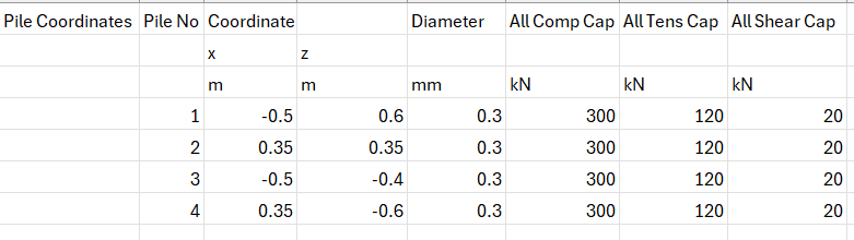
5. Clicking Yes opens the file which displays the information of the pile coordinates, diameter and allowable pile capacities
The export is useful when just a few coordinates need to be modified based on field data or creating an irregular pile pattern from a regular pile pattern that is automatically created by using the various pile pattern layouts on the Layout tab.
Importing Pile Coordinates from an Excel file
Use the following format to import pile information created in Excel to bring into the products on the Pile Layout page.
Then follow the steps below to import the pile information:
1. Click on "Import from Excel" button on the Coordinates tab of Pile Layout page
2. Select the Excel file that has the information represented as in the table above
3. After a successful import, the table displays the values from the Excel file
4. If the pile locations do not immediately reflect the change, navigate to another page and return to Pile Layout page to view the change
Changing the pile coordinates on the Coordinates tab and navigating to another row immediately reflects the pile location change based on the revised coordinates.