Default footing and pier geometries are created when a new workspace is created in Foundation3D and in Mat3D. In Foundation3D, the default geometries are different for equipment workspaces than miscellaneous workspaces.
The default footing dimensions are based on the workspace settings and the equipment geometry information. For eg for a pile supported footing, the default footing dimension is computed as the first formwork dimension + the pile parameters such as min pile spacing and pile edge distance.
The default pier dimension is also based on equipment geometry information and the first formwork dimension.
Exchanger, Horizontal Vessel:
A new exchanger workspace automatically creates two footings - FixedFooting, SlidingFooting each with one pier - Fixed Pier and Sliding Pier respectively.
If the exchanger workspace is imported from a spreadsheet, the missing pieces are automatically created.
Vertical Vessel, Miscellaneous:
A new vertical vessel or a miscellaneous workspace automatically creates one footing with one pier
If a vertical vessel or a miscellaneous workspace is imported from a spreadsheet, the missing pieces are automatically created.
The footing plan view displays the location of the piers on the footing and the footing dimensions. When the mouse hovers over the plan view, the cursor changes from the arrow type to magnifying glass type. Clicking anywhere on the plan view image where the cursor is magnifying glass type will open or pop-out another window that shows a much larger image of the plan view. The window can be expanded by grabbing the corners with the mouse to a desired size. Multiple pop-out windows can be displayed depending on the number of footings in the workspace. The pop-out windows will continue to display while navigating through various input and output pages. Clicking the close button on the pop-out window or clicking the back button on the main application window will close all the opened pop-out windows.
The following information is input on this page under the Footing Geometry section:
Footing Name: This is the footing name which can be different from the workspace name and is displayed on the Layout page. In order to avoid text clutter on the Layout page, a short name is preferable
Support Type: Select Soil Supported or Pile Supported
Shape: Select the desired shape of the footing from the available drop down values
Final Grade Elevation: This refers to the final ground elevation at the foundation (Prior to 2021R2 release, it was simply called "Grade Elevation")
Natural Grade Elevation: The natural grade elevation at the foundation location. This elevation is used to compute the allowable bearing pressure below the footing. In an existing workspace created prior to version 2021R2, and in a new workspace, the natural grade elevation is set to the same value as the final grade elevation. When the natural grade elevation is below the base of the footing, a validation error displays asking the user to reset the elevation.
Size: Depending on the footing shape, the footing dimensions are entered
Thickness: The constant footing thickness is entered here
Footing depth below grade: The distance between the bottom of the footing and the grade elevation is entered here. The soil cover is calculated as the difference between footing depth below grade and footing thickness and displayed
Offset in X and Z Direction: These refer to the offsets of the center-line of the footing from some reference point. These values are used to place and display the foundations in Layout and Layout3D
Rotation Angle: The footing rotation angle - clockwise rotation is positive
Number of Identical Foundations: The number entered here is used to obtain the total material quantities and costs of multiple identical foundations
Irregular Footings:
If an irregular footing type workspace is created, an option "Use uniformly spaced reinforcement arrangement" is displayed on this page. The default option is to not use uniformly spaced reinforcement arrangement.
The resize tab under the Footing Geometry section on the Footing Geometry page allows the footing size to be expanded or shrunk to the desired dimensions. The 2 options of "Keep Existing Offsets" and "Keep Existing Load Positions" allows keeping the load elements at the same offsets from the new center of the footing or allows keeping the load elements at the same locations when the footing size is expanded or shrunk. The "+" and "-" signs at each side of the footing provides a way to increase or decrease the footing size in positive X, negative X, positive Z and negative Z directions. For eg clicking on the bottommost "+" sign will increase the footing dimension in the negative Z direction by an amount indicated in the footing size increment field. The footing dimensions listed will change according to the changes made using the "+" or "-" signs.
Strap Footing:
If a strap foundation is created by joining two adjacent footings with a strap beam, the Footing Geometry page shows a different arrangement of tabs in the right pane of the window. For eg is say the two footings are called F & F1, and if they are strapped together with a strap beam, the tab at the top will display S-F-F1 indicating a strapped footing with a strap beam between footing F & F1. Under this main tab S-F-F1, 3 sub tabs will be displayed F, F1 and S-F-F1. Clicking on footings F & F1 will display the same information as displayed for non-strapped footings, i.e. Elevation View, Plan View and a Footing Geometry section where footing information may be entered. Clicking on S-F-F1 displays the Elevation view, Plan view and Strap Geometry along the strap direction.
Strap Geometry Section:
The strap geometry section on this page displays the values that may be changed to define the strap beam geometry.
Description: Edit this field to change the name of the strap beam connecting the two footings
Connection Type: This is a label only that automatically updates the type of connection that strap beam has with the two piers/ footings depending on how the top of strap beam connects to the piers/footings. The 4 different possible connections are:
Footing to Footing: When the top of the strap beam aligns with the top of the two footings, the connection type is called Footing to Footing
Pier to Pier: When the top of the strap beam connects to the two piers of each of the two footings, the connection type is called Pier to Pier
Pier to Footing: When the top of the strap beam on the left side connects to the pier of the left footing and on the right side connects to the right footing, the connection type is called Pier to Footing
Footing to Pier: When the top of the strap beam on the left side connects to the left footing and on the right side connects to the right pier of the right footing, the connection type is called Footing to Pier
Top Elevation: The top of the strap beam by default is set to align with the top of the two footings. However if this configuration needs to be changed, enter a different value for Top Elevation so that the top of the strap beam can connect to the two piers or to a pier and a footing depending on the top elevation of the two footings.
Bottom Elevation: The bottom of the strap beam by default is set to align with the bottom of one of the footings. If this must be changed, enter a different value in Bottom Elevation.
Length between Footings: Regardless of the strap beam connection to the two piers/footings, this value is a calculated value representing the distance between the two footings.
Width: Change the strap beam width to a desired value.
Import Footing Geometry:
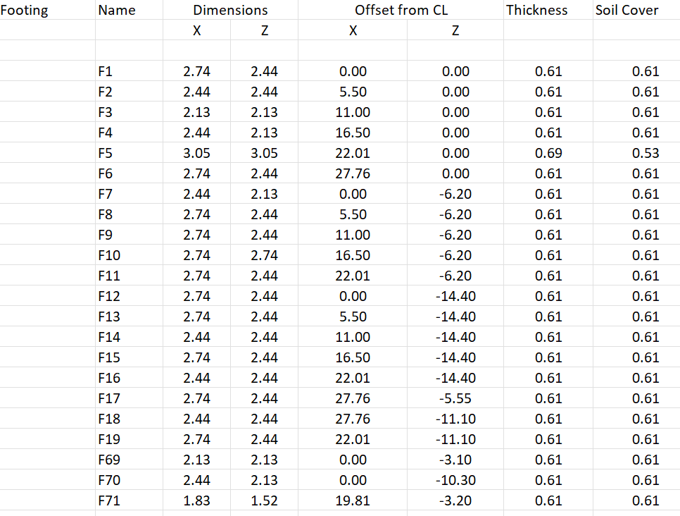
To import footing geometry of one or more footings from Excel, click the button with a tool tip "Import the footing geometry from a well formed Excel file" on the Footing Geometry page under Inputs. Select the Excel file that contains the footing geometry information in the Open dialog that displays. If the Excel file is in the correct format as displayed in the sample table below, the footing geometry will be imported in the Footing Geometry page. If the import completes successfully, a message displays "Footing geometry import completed successfully".
The import assumes that the units in the Excel file are the same as those of the workspace settings input units, the footings are rectangular in shape and the offsets listed in the Excel are offsets from some common reference point.