For a soil-supported foundation, an irregular-shaped footing can now be designed in Mat3D. To create an irregular footing workspace, refer to Creating a New Workspace.
Once an irregular footing workspace is created, the irregular footing geometry is created on the Footing Geometry page under Inputs. This page displays 2 tabs - Overview and Designer.
Overview:
This tab displays the footing plan view, elevation view and the footing geometry section. When the irregular footing is created initially using the Default Data option in create workspace wizard, the footing thickness and the depth below grade are set based on the values specified in the Geometry Defaults page of the Project Settings. The footing plan view is blank and the footing elevation view simply shows the GR EL at 0 and the footing thickness value without the footing.
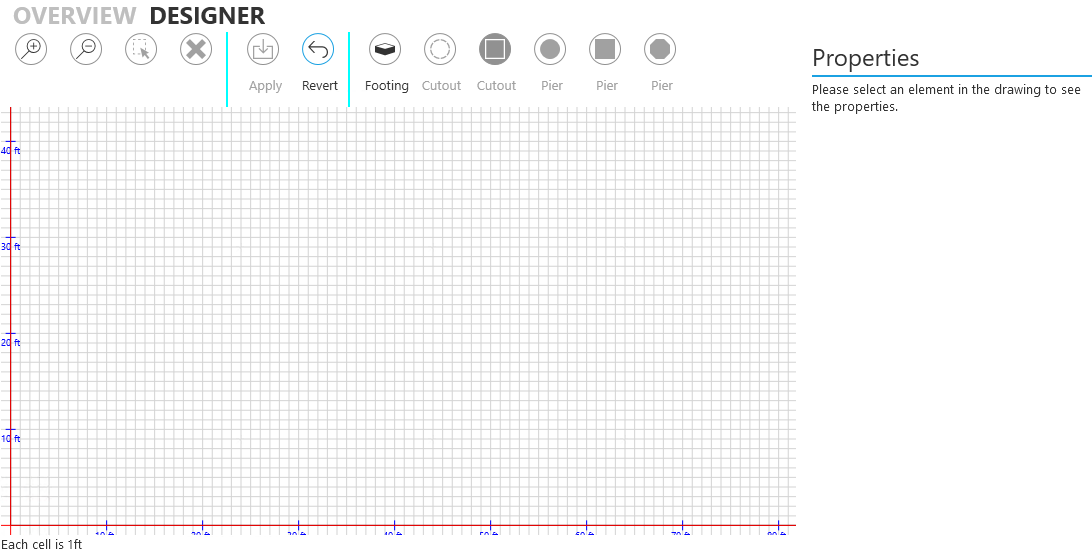
Designer:
This tab is where the irregular shaped footing geometry is created. It displays a grid with markings on the X axis and the Z axis to help create the geometry. The grid scale is displayed in the bottom left corner of the canvas. The buttons at the top of the page are used to create objects such as the footing, piers on the footing and to provide navigation. The Properties section to the right displays the properties of each of the elements The page looks as follows:
The description or functionality of the buttons from left to right is as follows:
1. Zoom in
2. Zoom out
3. Select
4. Delete or Remove
5. Apply changes
6. Revert changes
7. Draw a footing
8. Draw a circular cutout or hole in the footing
9. Draw a square cutout or hole in the footing
10. Draw a circular pier on the footing
11. Draw a square pier on the footing
12. Draw an octagonal pier on the footing
To create a footing, select the "Footing" button and start drawing the desired irregular shaped footing with vertices.
Notes:
1. The designer is meant to create an irregular shaped footing with piers and cutouts. It is a simple user interface and is not meant to mimic a CAD program with various drawing functionality options
2. Once started the footing geometry must be completed fully. It is not possible to save a partially created footing geometry or redo a section of the footing geometry. Therefore before creating the irregular shaped footing geometry, it may be useful to list the distances of the vertices from each other on paper so that the footing geometry can be created successfully in one shot.
3. Depending on the footing geometry that must be created, select the best possible grid scale by zooming in or out such that the entire footing geometry can be drawn in one shot. It is not possible to start drawing the footing geometry and then zooming in or out to complete the rest of the geometry.
4. To start from scratch in case the footing geometry did not start correctly as desired, use the Esc key.
5. To change pier properties such as shape, reinforcement ratio etc. after the footing geometry has been created, simply navigate to the Pier Geometry page and make the desired changes.
The requirements in creating a footing are as follows:
1. The footing must be a closed polygon
2. The footing cannot have crossed edges
The red cross-hair lines indicate the mouse position from a reference point. When the geometry is being created, the mouse position is with respect to the last drawn vertex and is indicated by a label "Footing edge is ...." just below the X axis. The value displayed is the distance of the current mouse location from the last drawn vertex. Once the footing geometry is complete, the mouse location is from the centroid of the footing which is dynamically calculated as the footing geometry is completed. The label then changes to "Distance from centroid of footing is ...".
The dashed magenta lines display the centroid location of the irregular shaped footing.
Once the footing geometry is created, use the appropriate pier or cutout buttons to place these elements on the footing. These elements can be placed in an approximate position without great accuracy since it is possible to refine the positions of these elements later. These elements can also be placed after zooming in to provide proper placement. For a pier, enter its name, shape, size in X and Z direction, X offset from origin, Z offset from origin, height and load type.
Use the "Apply" button to save the geometry if it is as desired or before navigating to any other page or "Revert" to completely erase the geometry and start from scratch.
To select a specific vertex and edit or change its coordinates, click the "Select" button (3rd button from the left) and select the vertex (indicated by a red filled color). The Properties section displays the vertex X and Z positions from the bottom left corner (0,0) of the grid canvas. To select a pier or a cutout click the "Select" button and click on the pier or the cutout to select it (indicated by a red filled color). The Properties section displays the pier or cutout size and the centroid position from the bottom left corner of the grid canvas. The pier properties also displays the pier name.
Once the irregular footing geometry is complete, enter loads on Load Cases page and load combination factors on Load Combinations page to complete the design.
Note: The default load cases are only created after a pier is created on the footing in the Designer tab of Footing Geometry page.